💡
This post gives a MATLAB code for 2D truss FEM and some FEM theory
FEM Procedure Build Load vector { P } \{P\} { P } Calculate [ k e ] [k^e] [ k e ] [ K ] [K] [ K ] Enforce Boundary conditions Postprocessing (calculate stress-strain, plots, etc.)%--- Calculate displacements ---------------------------------------------%
% Build global load vector
[P]=buildload(X,IX,ne,P,loads,mprop);
% Build global stiffness matrix
[Kmatr]=buildstiff(X,IX,ne,mprop,Kmatr);
% Enforce boundary conditions
[Kmatr,P]=enforce(Kmatr,P,bound);
% Solve system of equations
D=Kmatr\P;
% Calculate element stress and strain
[strain,stress]=recover(mprop,X,IX,D,ne,strain,stress);
%--- Plot results --------------------------------------------------------%
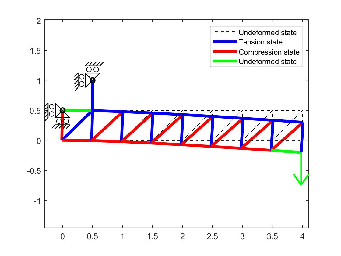
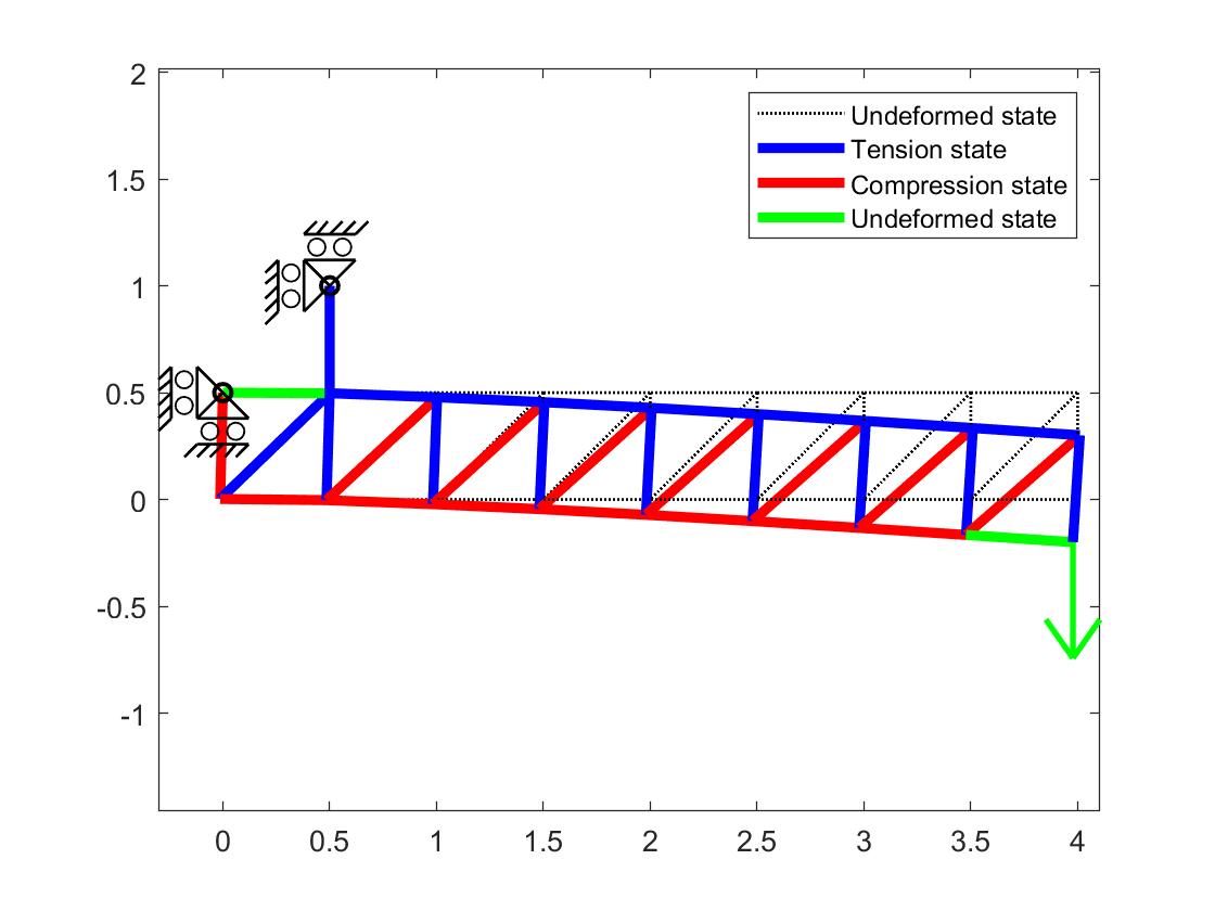
PlotStructure(X,IX,ne,neqn,bound,loads,D,stress) % Plot structure Virtual Work Principle ∫ V { δ ε } T { σ } d V = ∫ S { δ u } T { F } d S + ∫ V { δ u } T { Φ } d V + ∑ i { δ u } i T { p } i \int_{V}\{\delta \varepsilon\}^{T}\{\sigma\} d V=\int_{S}\{\delta \mathbf{u}\}^{T}\{F\} d S+\int_{V}\{\delta \mathbf{u}\}^{T}\{\Phi\} d V+\sum_{i}\{\delta \mathbf{u}\}_{i}^{T}\{p\}_{i} ∫ V { δ ε } T { σ } d V = ∫ S { δ u } T { F } d S + ∫ V { δ u } T { Φ } d V + i ∑ { δ u } i T { p } i For truss elements, displacement and external forces only applied in nodes, surface traction ({ F } = 0 \{F\}=0 { F } = 0 { Φ } = 0 \{\Phi\}=0 { Φ } = 0
∑ e δ ε N e L 0 e = { δ D } T { P } \sum_{e} \delta \varepsilon N^{e} L_{0}^{e}=\{\delta D\}^{T}\{P\} e ∑ δ ε N e L 0 e = { δD } T { P } 2D Truss element DOFs Where displacement of a truss element { d } = { u i v i u j v j } T \{d\}=\left\{\begin{array}{llll}u_{i} & v_{i} & u_{j} & v_{j}\end{array}\right\}^{T} { d } = { u i v i u j v j } T N e = A e E ϵ N^e=A^eE\epsilon N e = A e E ϵ L 0 e L_0^e L 0 e
ε = L 1 − L 0 L 0 = Δ u Δ x + Δ v Δ y L 0 2 = { d } T 1 L 0 2 { − Δ x , − Δ y , Δ x , Δ y } T = { d } T { B ˉ } = { d } T { B 0 } \varepsilon=\frac{L_{1}-L_{0}}{L_{0}}=\frac{\Delta u \Delta x+\Delta v \Delta y}{L_{0}^{2}}=\{d\}^{T} \frac{1}{L_{0}^{2}}\{-\Delta x,-\Delta y, \Delta x, \Delta y\}^{T}=\{d\}^{T}\{\bar{B}\}=\{d\}^{T}\left\{B_{0}\right\} ε = L 0 L 1 − L 0 = L 0 2 Δ u Δ x + Δ v Δ y = { d } T L 0 2 1 { − Δ x , − Δ y , Δ x , Δ y } T = { d } T { B ˉ } = { d } T { B 0 } The VWP hold for any { D } \{D\} { D } { d } \{d\} { d }
[ ∑ e A e E L 0 e { B 0 } { B 0 } T ] { D } = { P } \left[\sum_{e} A^{e} E L_{0}^{e}\left\{B_{0}\right\}\left\{B_{0}\right\}^{T}\right]\{D\}=\{P\} [ e ∑ A e E L 0 e { B 0 } { B 0 } T ] { D } = { P } [ K ] { D } = { P } [K]\{D\}=\{P\} [ K ] { D } = { P } [ k e ] [k^e] [ k e ] [ k e ] = A e E L 0 e { B 0 } { B 0 } T = A e E ( L 0 e ) 3 [ Δ x 2 Δ x Δ y − Δ x 2 − Δ x Δ y Δ x Δ y Δ y 2 − Δ x Δ y − Δ y 2 − Δ x 2 − Δ x Δ y Δ x 2 Δ x Δ y − Δ x Δ y − Δ y 2 Δ x Δ y Δ y 2 ] \left[k^{e}\right]=A^{e} E L_{0}^{e}\left\{B_{0}\right\}\left\{B_{0}\right\}^{T}=\frac{A^{e} E}{\left(L_{0}^{e}\right)^{3}}\left[\begin{array}{cccc}\Delta x^{2} & \Delta x \Delta y & -\Delta x^{2} & -\Delta x \Delta y \\\Delta x \Delta y & \Delta y^{2} & -\Delta x \Delta y & -\Delta y^{2} \\-\Delta x^{2} & -\Delta x \Delta y & \Delta x^{2} & \Delta x \Delta y \\-\Delta x \Delta y & -\Delta y^{2} & \Delta x \Delta y & \Delta y^{2}\end{array}\right] [ k e ] = A e E L 0 e { B 0 } { B 0 } T = ( L 0 e ) 3 A e E Δ x 2 Δ x Δ y − Δ x 2 − Δ x Δ y Δ x Δ y Δ y 2 − Δ x Δ y − Δ y 2 − Δ x 2 − Δ x Δ y Δ x 2 Δ x Δ y − Δ x Δ y − Δ y 2 Δ x Δ y Δ y 2 B 0 B_0 B 0
Assembly of element matrix to global matrix Global stiffness matrix [ K ] = ∑ e [ k e ] [K]=\sum_e[k^e] [ K ] = ∑ e [ k e ]
Enforce Boundary Conditions
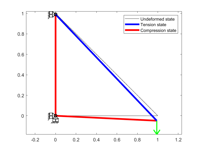
Solve { D } \{D\} { D } [ K ] { D } = { P } [K]\{D\}=\{P\} [ K ] { D } = { P } Example BC: x=y=0 at node 1, x=0 at node 2 and Fy=-0.01 at node 3
How do you like this Post? Attachment Download the code from below GitHub repo 👇below, please give a five-star 👆
https://github.com/hyhsuen/FEM2DTruss
Acknowledgment: Content Originally from Notes and Exercise for the Course Finite Element Methods 41525, Ole Sigmund, Department of Mechanical Engineering, Technical University of Denmark

 Henry
Henry


